
| |
| Lew started the CCD Camera cookbook project this spring. The study of binary stars, including dwarf novae, is the purpose of the project. Also, take a look at the IAPPP CCD seminar held at Lake Arrowhead. This will open a a separate window by your browser. |
| Weekly progress reports | ||
| May 18 | ||
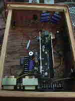 |  | 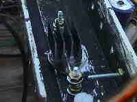 |
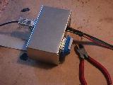
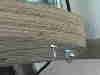
| The fan will get a shroud to duct the air over the heat sink. The heat sink (operating at +12V) is mounted on a nylon standoff and the power transistor 2N3055 gets an additional heat sink on top which is held down by a wire strung between posts. | ||
| May 25 | ||
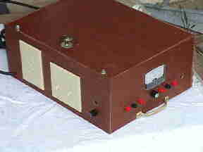 |  | |
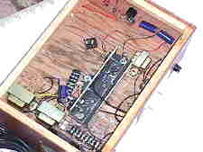
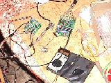
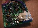
| Power supply: Completed. Ordinarily Lew's philosophy is to prefer function over form, but the ugly construction of the power supply brings a true appreciation of a neatly laid out printed circuit. | ||
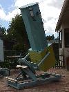 | 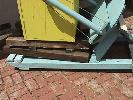 |  |
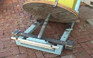
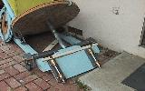
| Scope rework: The telescope with the jerky tangent arm drive removed. | The tube assembly was cribbed for support | and the support structure removed. |
| The small casters were removed from under the frame of the mount and an outrigger assembly with larger wheels was installed. It facilitates moving the telescope, and when ready to observe, supports are inserted beneath the frame to lock the telescope in position. | ||
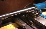 |  | 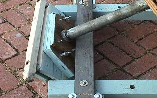 |
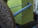
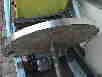
| The drive will be converted to a friction drive with a 1.5 inch diameter drive roller (being turned here) on a 35.9 inch diameter wheel. | The rough cut plywood wheel consists of 3 pieces of 3/4 inch plywood. It is now on the polar shaft and attached to the yoke. | The polar axle lower end sits in a bearing held in a wooden frame. The pipe collar is expoxied into the bearing. |
| May 31 - Polar axis lower ball bearing set in wooden frame Drive Friction pinion shaft stock cut for east and west wheels Pinion shaft (1.5 inch stainless steel rod) drilled for 1/2 inch drive shaft and turned. | ||
| June 7 - RA Wheel pinions mounted. Circuit board passed regulator test. Encoders and a Black Box for the computer position information were received from Software Bisque. Brian at Software Bisque faxed info on the BBox connections and has sent connectors and more information for the connections. Thanks, Brian! | ||
 |  |  |
| Stainless steel is "grabby" and got the 1/4-20 tap so the hold down is now a 10-24 screw in a loose fitting threaded hole! | The rollers for the RA wheel are assembled and the gear reducer fits in the lower end of the left roller | The boards are being tested |
| As long as we are talking about mistakes, Here's Lew's Double goof: The Drive pinion roller was bored to accept a 1/2 inch shaft. Turns out the input shaft of the 60:1 speed reducer is 1/2 inch but the output is 5/8. (Goof 1 - not measuring the shaft but relying on a defective memory). So a trip to the hardware store for a 5/8 inch bit solved the problem and the hole was bored out. It is a stepwise process anyway. When the new 5/8 bit was put away, a twin was lying in the drawer awaiting company. (Goof 2 - buying a tool forgetting there was one in the drawer.) That was the same day the lathe direction was reversed before stopping the lathe, blowing out the switch. It would still work in one direction so the lathe would work, but no milling could be done. So it was a day with 3 goofs, 2 that cost money. It is nice to have 2 5/8 inch bits, tho! | ||
| June 14 - Circuit boards tested and interface card boxed. Camera parts turned to OD specs. | ||
| Machining of camera parts: Camera body, eyepiece tube, Heat exchanger and End cap machined to specified OD and flat faces. Inside of tubes awaiting boring bar from Smithy. | ||
 |  |  |
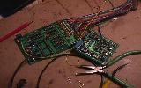
| Circuit Boards: completed and tested. Two resistors required lowering their values about 10% with parallel resistors. One cold solder joint found. Cables made up and the plugs wired. Interface card boxed. Warning to others doing testing: The VR1 and VR3 voltage regulators get HOT! Don't burn yourself! | ||
 | 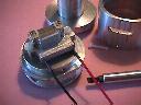 | |
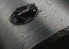
| June 21. The solstice is welcomed by the finishing of machining and assembly of the camera parts. The CCD chip, the TI 245 is wired to the J2/J3 plug using tiny wires. They were coated with acrylic varnish for insulation. Assembly was time consuming but the chip was wired and tested. It responds to light, giving a blank screen of varying intensity depending upon the light level. Work remaining on the camera includes putting in the window and fastening the brackets and preamp card case onto the camera body. The interior of the eyepiece tube and forward interior of the camera body and end cap will be painted black. The tubing for the heat exchanger was fitted with the connectors for coolant and was stretched about 20% in length to allow more circulation of the secondary coolant through the heat exchanger. Goofs - One big one. One slot for the peltier wires was cut into the wrong end of the camera body, but will be filled with epoxy. | ||
| June 28 | ||
 |  | 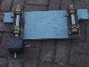 |
| The fork was reinforced with the two threaded rods which also locate the wheel. | Transistor Q7 was given a foam blanket | The speed reducer fits into the west pinion of the friction drive. |
| The interior of the eyepiece tube and end cap were painted black and the window was installed. The window material is acrylic to cut down on the possibility of condensation on the window. The brackets for the preamp cover were fitted and the bottom of the camera was sealed with silicone sealant. The top will be sealed after final testing. | ||
| July 5 | ||
 |  |  |
| The drive train was installed under the rough wheel. | The wheel is smoothed for the aluminum band. Half of the wheel is done, the bottom half will be done on the next work project weekend, later in July. | The space between the aluminum band and the wheel will be filled with Bondo to solidify the wheel and fill in imperfections. |
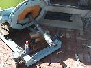
There were no "goofs" this week, however the drive wheel on the belt sander de-laminated under heavy heat and load (the wheel is being reduced in diameter by almost an inch from the rough cut size). The choice between economy (ordering replacement parts for the unit) or speed (purchasing a new one) was settled in haste's favor. The new unit (Ryobi) is better and hogs out the wood quickly. | ||
| July 12 - No activity this week! | ||
 |  | |
| July 19. | ||
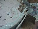
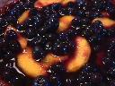
| The wheel is smoothed for the aluminum band and Bondo is applied to the gap between the wooden wheel and the Al band, using a jig for diameter control. Half of the wheel is filled, the next half will be done on the next work project weekend, in early August. | Rebecca (our elder daughter) baked a yummy blueberry pie for Lew's 53rd birthday. | |
There were no "goofs" this week, other than the drips and drabs resulting from pouring the bondo (thinned with epoxy resin) into the gap which is stopped with duct tape. You Star Wars fans will recognize Duct tape as "The Force". It has a Dark Side, A Light Side and it holds the universe together! | ||
| August 17. | ||
 |  |  |
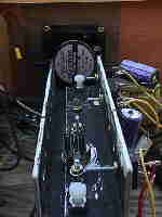
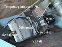
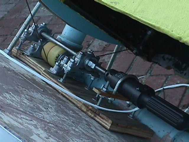
| The drive wheel has been banded and work returned to the drive. Here the Right Ascension slewing pulleys have been fitted. | The slewing motor will need to have sufficient torque and speed to overcome the drive train friction through the differential and gear reducer and move the scope reasonably quickly. Here a reversible drill is used in testing. A wimpy battery powered screwdriver bogged down. | For the first time the camera was placed on the telescope and turned on. The 1.25 to 2 inch adapter on the focuser will need to be changed with another one from one of the other telescopes to reach to the focus plane. the camera could be hand held and an image obtained with the short 0.3 second focus exposures. The camera was not cooled for this first check of operability and the thin plastic film over the CCD has not been removed yet. It will be removed when the camera is sealed and all tests verify it is working acceptably. |
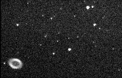
| August 23. The image above is the first one taken of a target object with the camera. It is an unfiltered 4 second exposure and (with a little imagination) the central 14th magnitude star in the ring nebula can be seen. Coma indicates the collimation of the telescope needs improving. | ||
| ||
| The cooling system for the camera was assembled (not shown here). | ||
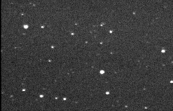 | A 4 second exposure on 8/22-23/98, cooled. Some place in Lyra or Cygnus. | |
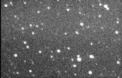 | A 15 second exposure on 8/22-23/98, cooled. This is just a random field in Cygnus. Polar alignment? WHAT polar alignment? | |
| There was one failure (I don't know if it can be considered a goof - at least not my goof). The windshield washer motor which operates the cooling system operated during the 4 hour test running continuously on Saturday night. On Sunday afternoon, it would not start - it was jammed or frozen. A wimpy "table top" fountain pump was purchased that has at most 2 feet of head and when the tubing system (that extends to about 9 feet height) was primed, it worked acceptably with a flow through the line of about 1 foot per second. A suggestion to others: Don't bother with the windshield washer motor - get one that will last more than 4 hours! | ||
| Two trips to Kazakhstan this fall delayed refinement of the camera. In October, the weather began to deteriorate, and now fewer nights are suitable for work. To facilitate collimating, the support for the primary mirror was modified slightly. This will make collimation easier. The camera had some condensation inside at the last test, and it will be opened and dried. Perhaps a dessicant connection will be added. Anyone having experience with dessicants (silica gel or anything else?) please | ||
| To keep weather off of the telescope and to allow it to remain in position so that realignment is not necessary every time the scope is used, A shed was built to cover the Telescope. The first version of the shed was a bit larger and met with resistance from Donna. She is happier with the cut down version. It snugly fits over the telescope. | 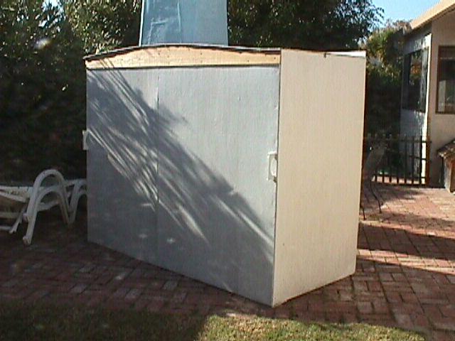
| |
|
The cooling system for the camera was assembled (not shown here). 8/29 - the external finder was relocated downward on the tube nearer the fork and screw eyes were added to use to tie cables to along the tube. | |
|
On the weekend of Aug 29, the motor was disassembled, lubricated and the spring arm for the brush reinforced with a drop of solder. A switch was put in the power line for the pump which now acts as a booster pump. The tubing was cut and a 5 foot extension was added in the middle so the tubing could be extended through the disk. The cables will be routed there, too. The disk for the declination axis was cut out and mounted. It will function as a large (46 inch diameter) pulley for the declination motions. It allows setting circles to be inscribed on the wheel. At a diameter of 45.1 inches, one degree spans 10 millimeters! | ||
| September 7 | ||
 |  | |
| The declination slewing motor is a battery operated screwdriver operating a friction driven urethane pulley. It operates a very large pulley (46 inches). The overall ratio between the screwdriver and the declination axis is about 120:1. | The camera on the telescope. | |
| The scope with the camera attached is to the right | 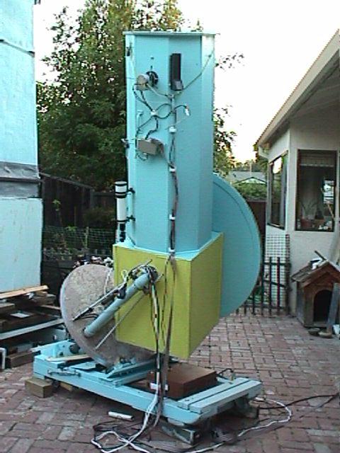 (a different picture) (a different picture) | |
| Jan 2-3, 1999. A dessicant tube was added to the camera body and the window moved to the top of the camera top plate. This has cured the window fogging problem experienced earlier. The first scientifically useful image was obtained of the field of AQ Eridani, a dwarf nova. Despite haze, high thin cirrus clouds and a full moon ~45 degrees away which caused some scattered light on one side of the field, the 8 stacked (8 sec.) exposures clearly show the 15.3 magnitude comparison star. The variable was fainter and not visible. A "V" filter was used. The focus and collimation are not yet right. The secondary mirror needs firmer support to hold the collimation at all angles of the telescope. | 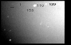 | |
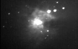 | M42, a bit fuzzy, exposed 8 seconds through a V (green) filter with a full moon adding to the background. | |
| Lew will post further progress (and admit to future goofs) as made. | ||
| Plans for the CCD Camera, Telescope Mount and Finder | ||
| CCD Camera | Build Cookbook CCD | Camera completed, in final testing |
| Telescope Mount | Convert from tangent arm drive to friction drive | 1.48 inch pinion driving 35.5 inch wheel |
| Finder upgrade | Provide alternate images to CCD from finder | Internal finder with switchable optical path |
| Drive | 1 rpm synchronous motor to 60:1 speed reducer | Shaft directly coupled to drive pinion |
| Digital telescope positioning | Installed encoders on RA & Dec axes | Link with TheSky using BBox ( Software Bisque) |
| Slewing and slow motions | ||
| Fast RA via differential from 100(+/-) rpm reversible motor A power drill motor will be used with a pulley and belt to the differential box | RA Slow Motion by variable frequency to synchronous motor | |
| Fast Dec - cable driven large wheel from friction driven small urethane wheel in turn driven by a power screw driver | ||
| Slow dec - screw drive moving the slewing assembly carriage via a 1 rpm dc reversible motor motor | ||
 let me have your advice.